Accelerometer Test
The first test is designed to apply different accelerations to the dampener to verify that the ferrofluid clumps in an effective manner at reasonable accelerations like that of a car crash.
Instron and Shimadzu Machine Test
The purpose of these two tests will be to confirm that the dampener is able reduce the force applied on the seat belt during an accident. By applying different loads to the dampener at varying voltages we hope to achieve the following:
-
Autonomous
-
Low Amperage used
-
The dampener does not interfere with standard seatbelt operation (non-intrusive)
-
The ferrofluid separates after testing when voltage is removed (re-useable)
The arduino could not be connected to the device for testing because the solenoid was not going into it. Instead Anthony set up visual feedback through an LED light that would indicate if the accelerometer successfully communicated with the on/off switch that would turn on the solenoid.
Our initial testing method was set up with magnets inside the cup in a way that the magnetic field was parallel to the damper. This was because we were not able to create a working solenoid that would function within our prototype. While extending the damper in the Shimadzu we were getting values between 250 and 300 N with this set up. We were uncertain if we were getting values this high because of the magnetic field we were creating or because of the friction within the damper. See Figure 1.
After not being able to gather convincing data with the magnetic field parallel to the damper, we reoriented the magnets so that the magnetic field was perpendicular to damper. During these tests the Shimadzu was consistently reading between 50 and 100N which is less than the previous tests but this was most likely due to the ferrofluid being more evenly distributed around the cup within the damper effectively reducing the friction. Due to the ferrofluid essentially acting as lubrication we also placed magnets around the outside of the damper in line with the magnets on the inside. The purpose of the additional magnets on the outside was to have them increase the magnetic field on the inside, making it harder for the ferrofluid to pass through the bleed holes of the cup. The magnets on the inside alone did not show any measurable change required to extend the prototype and unfortunately we could not show any difference in force required to engage the damper with the magnets on the outside as well. See Figure 2.
Both of the tests with the magnets did not show any convincing evidence that we were able to increase the force required to extend the damper. The friction between the cup and the damper wall as well as the force needed to move the ferrofluid through the bleed holes required much more force to overcome than any magnetic field we were able to create.
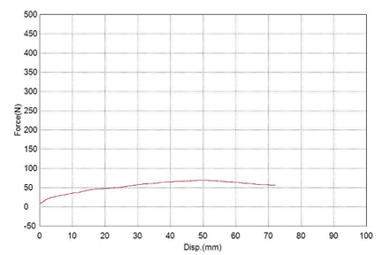
For the final test design we wrapped a large solenoid around the outside of the prototype. Wrapping the solenoid on the outside should have produced a stronger magnetic field in the center of the solenoid in comparison to our original design in which we would have relied on the weaker magnetic field on the outside of the solenoid. The magnetic fields on the inside of a solenoid are inherently stronger than those on the outside of the solenoid. While running varying levels of amperage through the solenoid the damper required roughly 30 N consistently to extend the prototype. Our DC voltage generator that we were using maxed out at 3 amps so we ran tests up until that point with no change in test results. See Figure 3.
After running the test with current through the solenoid, we ran a control test without magnets or the solenoid. Unfortunately there was no discernable difference between the solenoid test graph and the control test graph meaning the solenoid was unable to increase the force needed to extend the damper. Our initial testing values with the magnets can be attributed to the high levels of friction and that is why our values only decreased as testing went on. After further research the reason that the solenoid may have failed was because the stainless steel we used was austenitic grade which did not allow the magnetic field to pass through the wall.
Unfortunately since the Damper did not meet our high expectations we chose not to read the field generated in the overall damper with the Hall effect sensor. The only purpose of the Hall effect sensor testing was to determine how strong the magnetic fields were in different stages of testing. Since we were unable to create a field that could increase the force required to extend the damper we deemed it unnecessary to test these fields. Testing was not completed as we intended, but we were able to collect some results. Because the solenoid would not be conducive to test with the prototype, we bought stack-able magnets to mimic an electromagnet field. We designed a piston cup seal that would be removable and we can test different amounts of magnets, in other words different strength fields. The down side is we had to take apart the bottom each time and replace whatever fluid is lost. We were unable to easily add or remove magnets because the fluid creeps around any material with a field making it relatively time consuming to change from one testing design to another. Another unsuspected problem was the leaking through the hollow piston rod because we did not make the epoxy seal we planned for the solenoid. In the initial tests the fluid was leaking out if the damper was extended to far or was not held in an upright position. Before the second round of testing, we replaced the button screw holding the damper together to one without the hole which stopped the leakage from the previous test.
.png)
.png)
Figure 1
.png)
.png)
Figure 2
.png)

Figure 3
